Heavy Gage OSL Bolted/Welded Clip Angles ( Fabricator Settings )

To specify this type of standard clip angle in the model :

  • Heavy Gage OSL Bolted/Welded Clip Angles are double clip angles that shop or field bolt to the supporting member (beam or column) and are designed as the supported beam's end connection when ' Heavy Gage ', ' Bolted ' (to supporting), ' Welded ' (to supported), and shop attach to ' Supporting ' (or ' Supported ') are specified in " Connection specifications " for auto standard , user defined or beam-window-specified clip angles.
  • For a joist, the required settings that result in a clip angle being designed using this clip angle configuration are ' Heavy Gage ', ' Bolted ' (to supporting), ' Welded ' (to supported).
  • If the Clip Angle Piecemarks table on this window is filled out, any standard piecemark on that table can be added as an existing material .
  • You can get a clip angle hanger connection for a column by selecting ' Clip angle ' as the column's " Input connection type " then checking the box for " Force ."
  • For vertical brace to beam & column framing situations, connection design attaches the vertical brace gusset plate to the column using the same clip angle configuration that is used to attach the beam to the column. A " Combine beam/vbrc clip angles " option in the beam's " Connection specifications " lets you specify whether or not those clip angles are combined.
  • Clip angles can also be used for the attachment of vertical brace and horizontal brace gusset plates in various framing situations.

home > project settings > fabricator > pIecemarking > | clip configurations | top


   To open this window :

You can open this window using any one (1) of the following methods:

Method 1 : Home > Project Settings > Fabricator > PIecemarking > Bolted/Welded Clip Angles > Heavy Gage OSL Bolted/ Welded Clip Angles .

Password protection: If a password has been set using the Change Setup Password utility, you can open this window only if you first enter that exact password.

home > project settings > fabricator > pIecemarking > | clip configurations | top


------ Settings ------


or

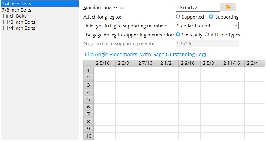
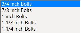
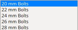
Each bolt diameter is a distinct clip angle configuration that needs to be set up separately. The tabs show imperial sizes when the " Available bolt diameters " is 'Imperial '. Metric sizes are shown when the " Available bolt diameters " is 'Metric '. If " Available bolt diameters " is set to 'Both ', the   primary dimensioning " Units " determine whether the tabs show imperial or metric bolt sizes.

Standard angle size: The angle section size for the specific bolt diameter tab that has been selected. The angle must be listed in the local shape file.

To enter an angle section size: Either type in the section size that you want (e.g., ' L4x3 1/2x5/16 '), or press the "file cabinet" browse button ( ) and choose an angle section from the list of angles in the local shape file .

Also: If you enter a size that has unequal legs, be sure to specify (below) whether you want to " Attach long leg to " the ' Supported ' or ' Supporting ' member.

Attach long leg to: Supported or Supporting . This applies when a " Standard angle size " with unequal legs has been entered. Example: The long leg for L3 1/2x3x5/16 angle material is the leg that is 3 1 /2 inches in length.
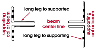
' Supported ' fastens the long leg of the angle to the supported beam or the knife plate of the joist.

' Supporting ' fastens the long leg of the angle to the supporting beam or column.

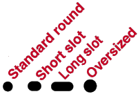
Hole type in leg to supporting member: Standard round or Short slot or Long slot or Oversized or User slot #1 or User slot #2 .

Effect on connection design: The hole type selected here applies to the clip angle leg that bolts to the supporting beam or column. Connection design creates holes per " Connection design method " specifications, determining the specific size of a hole based on the hole type selected here and the bolt diameter selected as the tab.

Use gage on leg to supporting member for: Slots only or All hole types .

' Slots only ' instructs connection design to apply the " Gage on leg to supporting member " only when the " Hole type in leg to supporting member " is ' Short slot ' or ' Long slot ' or ' User slot #1 ' or ' User slot #2 '. On standard round holes, connection design sets the gage based on the " Heavy gage, inside holes " center-to-center distance and the web thickness of the supported beam.

' All hole types ' instructs connection design to apply the " Gage on leg to supporting member " for all hole types, including standard round holes.

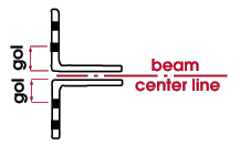
Gage on leg to supporting member: The distance (in the primary dimension " Units " or other units ) from the outside corner of the clip angle to the center of the first column of holes on the outstanding leg (on the leg that bolts to the supporting beam or column).

For slots, connection design may apply a different GOL than that which is entered here in order to permit bolts to fit in the slots at the " Heavy gage, inside holes " center-to-center distance.

home > project settings > fabricator > pIecemarking > | clip configurations | top


------ Clip Angle Piecemarks ------

To edit the Clip Angle Piecemarks table, your current Fabricator needs to be the Master Fabricator . If your current Fabricator is not the Master Fabricator , piecemarking routines will continue to reference the version of the Clip Angle Piecemarks table in the Master Fabricator and, when connection design creates a clip angle that exactly matches a clip angle defined on that table, SDS2 piecemarking assigns the piecemark that is entered for that clip angle. This ensures that standard piecemarks for clip angles come from a single setup source, regardless of your current Fabricator. This table is disabled (grayed out) when your current Fabricator is not the Master Fabricator .

For clip angles in this configuration: Connection design sets GOLs according to the " Heavy gage, inside holes " center-to-center distance and the web thickness of the supported beam. The number of rows of bolts are determined by the shear load on the beam. If a standard piecemark from this table matches the GOL and number of rows of bolts in the actual designed clip angle, that piecemark is assigned. To get a user-added clip angle from this table, you can select the clip angle's standard piecemark when adding an existing material -- this applies even if the clip angle with the standard piecemark has not yet been placed in the 3D model.

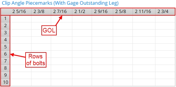
Column heads (GOLs): Each column head on this table is a GOL (gage on outstanding leg). These GOLs are calculated from the " Heavy gage, inside holes " center-to-center distance that is entered in Clip Angle Settings .

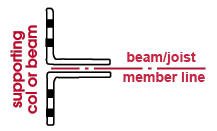
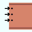
Rows: Each row on the Clip Angle Piecemarks table is a number of rows of bolts. Since the beam's end in the example below takes a clip angle with 3 rows of bolts, you would enter the submterial mark for that beam end's clip angle to the appropriate column in row 3 of the table.

Number of rows = ' 3 '

To make entries: Click the cell that corresponds to the GOL (gage on outstanding leg) and number of rows of bolts desired. Type in a clip angle standard piecemark of up to 61 characters. The GOL is measured from the heel of the angle to the center of the hole (or slot).

Slots minimize the number of different piecemarks. This example shows a scheme that a fabricator might use for assigning standard piecemarks to clip angles with slots:

Navigating the table: Press Tab or Tab + Shift to move from cell to cell on the table. Other ways to move from cell to cell are by using the up/down arrow keys on the keyboard or by repositioning the mouse pointer then clicking. For more information, see text entry widgets .

Example: To Standard Clip Angle Settings , you have entered a " Heavy gage, inside holes " center-to-center distance of ' 5 1/2 '. Your shop has in stock a barrel full of heavy gage welded clip angles with gages on the outstanding leg of 2 1/2 inches and three rows of 7/8 inch bolts . The piecemark used to identify angles in this barrel is 40_3_14k . To make certain that the correct piecemark is assigned to this clip angle, you open this window and select the " 7/8 inch Bolts " bolt diameter tab . You then enter ' 40_3_14k ' to this table in row 3 under the column for 2 1/2 . Heavy gage welded clip angles with gages of 2 1/2 inches are designed where heavy gage shop welded double clip angles are specified on beams with 1/2 inch webs and the inside holes center-to-center distance is 5 1/2 inches . They are designed with three rows of bolts when the shear load on the beam and depth of the beam is sufficiently large.

home > project settings > fabricator > pIecemarking > | clip configurations | top


   To close this window :


"OK" (or the Enter key) closes this window and saves the settings on it to the current Fabricator that is currently loaded in your current Job . To change to a different Fabricator , Home > press "fabname" > double-click the Fabricator you want.

Note 1: If, on this window, you changed a clip angle definition for which a standard " Clip Angle Piecemark " was assigned to clip angles in your current Job, then validation informs you that there is a piecemarking conflict and gives you options for changing the marks on clip angles generated using the old (unrevised) definition. Click here for more information.

Note 2: If you want changes to this window applied to particular members, you can Process Selected Members then Process and Create Solids . Or you can Mark Members for Processing then Process and Create Solids .

"Cancel" (or the Esc key or the button) closes this window without saving any changes made to it.

"Reset" undoes all changes that you made to this window since you first opened it. The window remains open.

home > project settings > fabricator > pIecemarking > | clip configurations | top